Difference between revisions of "IOT100 - Lesson 5 - Controlling an LED from the Cloud"
| (8 intermediate revisions by the same user not shown) | |||
| Line 1: | Line 1: | ||
'''Project Goal: ''' To receive commands from the internet to control the Huzzah. | '''Project Goal: ''' To receive commands from the internet to control the Huzzah. | ||
| − | |||
| − | |||
This lesson will cover: | This lesson will cover: | ||
| Line 81: | Line 79: | ||
=== Testing and Using Your Dashboard === | === Testing and Using Your Dashboard === | ||
| − | To use the dashboard | + | To use the dashboard, go to the io.adafruit.com website either from a computer, or from an internet enabled phone. Log in, and find your Dashboard named Lesson5. Now whenever you switch from ON to OFF and vice versa, the Adafruit Cloud will send a message to any devices that have subscribed to the LedSwitch datafeed. |
| + | |||
| + | So let's create the circuit and the program now.... | ||
== Wifi Connection Parameters == | == Wifi Connection Parameters == | ||
| Line 92: | Line 92: | ||
[[File:IOT100-lesson3.png|500px]] | [[File:IOT100-lesson3.png|500px]] | ||
| + | |||
| + | == Enable Some Libraries == | ||
| + | |||
| + | We need three additional libraries within the Arduino IDE. So start up the IDE, and go to Sketch -> Include Library -> Manage Libraries... | ||
| + | |||
| + | Scroll down to find the ''Adafruit IO Arduino'', then click the Install button (if you can't, select the latest version from the dropdown list). | ||
| + | |||
| + | Then scroll down and do the same for the ''Adafuit MQTT Library''. | ||
| + | |||
| + | Finally, do the same for the ''ArduinoHttpClient'' library. | ||
| + | |||
| + | '''Note:''' There may be a requirement for a specific version of the ESP8266 Board software (that we installed in Lesson 1). You might want to check that ''Tools -> Board -> Boards Manager'' has version 2.4.2 Installed for the '''esp8266''' boards. | ||
== Create the Program == | == Create the Program == | ||
| Line 101: | Line 113: | ||
We have not needed it yet because out programs have been pretty simple, but sometimes you need to see what a program is doing, as it executes, to figure out why something is not working correctly. Many modern development IDEs have 'debuggers' where you can manually execute your code line by line; unfortunately, because our code is uploaded and runs on the Huzzah microprocessor, that is not an option. So we have to revert back to the old fashioned debugging - print statements. | We have not needed it yet because out programs have been pretty simple, but sometimes you need to see what a program is doing, as it executes, to figure out why something is not working correctly. Many modern development IDEs have 'debuggers' where you can manually execute your code line by line; unfortunately, because our code is uploaded and runs on the Huzzah microprocessor, that is not an option. So we have to revert back to the old fashioned debugging - print statements. | ||
| − | There is an iconic button on the top right over every sketch: | + | There is an iconic button on the top right over every sketch (it kind of looks like a magnifying glass with a dot in the middle): |
| − | + | [[File:ConsoleStartup.png|300px]] | |
Click that to open another window called the Console. Never open the console when you are uploading a sketch - the upload will fail. Open the console before you upload, or after. When the console opens, made sure it's baud rate is the same as the value you specify in the Serial.begin(); call in your code (or you will see funny looking characters. | Click that to open another window called the Console. Never open the console when you are uploading a sketch - the upload will fail. Open the console before you upload, or after. When the console opens, made sure it's baud rate is the same as the value you specify in the Serial.begin(); call in your code (or you will see funny looking characters. | ||
| − | + | [[File:ConsoleScreen.png|500px]] | |
In order to use the Console, you need to initialize it within the setup() loop: | In order to use the Console, you need to initialize it within the setup() loop: | ||
| Line 304: | Line 316: | ||
Serial.println(message); | Serial.println(message); | ||
if ( message == "ON" ) { | if ( message == "ON" ) { | ||
| − | + | digitalWrite(LEDPIN,HIGH); | |
} | } | ||
else { | else { | ||
| Line 311: | Line 323: | ||
} | } | ||
</pre> | </pre> | ||
| − | |||
=== Compile and Run === | === Compile and Run === | ||
Latest revision as of 02:47, 28 January 2019
Project Goal: To receive commands from the internet to control the Huzzah.
This lesson will cover:
- connecting to the Adafruit IO Cloud
- configuring a datafeed on the cloud
- subscribing to events from the cloud
- message handlers
- using Serial output to trace a program
Contents
Overview
One of the easiest ways to receive extrnal commands on the Huzzah is to "subscribe" to a datafeed from the Adafruit Cloud. we define a datafeed on the Cloud website by giving it a name, and define the type of values it has. Then we can add a dashboard on the Cloud to let us control that value with a phone, or another computer. When the Huzzah starts up, it will "subscribe"to that datafeed, so that whenever the value of the datrafeed is changed, the Cloud will automatically send us a message with the new value.
Setting up the Datafeed
Connect to your Adafruit IO Cloud Account
First, go to the Adafruit IO Cloud website and login with the account you created back in Lesson#1.
Enter your username/email and password, and sign in.
Create a New Datafeed
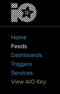
Create a datafeed called LedSwitch. To do this, click on the Feeds link to the left of the screen:
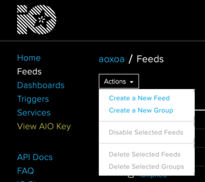
Then click on the Actions pulldown, and click on the Create a New Feed link.
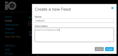
Fill in the information. The Description is optional, but for this lesson, make sure that the Name is LedSwitch . (capitals are important).
Click the Create button, and you should see a list of any other feeds you have created (probably none at this point), plus the one you just created:
Create a Dashboard to Control the Datafeed
A Dashboard lets us control (or, in a later lesson, view) data from a Datafeed.
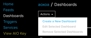
Click on the Dashboards link to the left, and then select Actions, and select the Create a New Dashboard.
Just like with the Datafeed, you will be asked to give the Dashboard a name, and an optional description. I would suggest naming the Dashboard "Lesson5".
This will display a blank dashboard. Select the Blue + icon towards the right side of the screen.
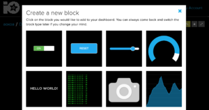
This will bring up a list of possible blocks / widgets to add:
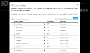
Select the ON/OFF switch in the top left. When you pick it, it will automatically bring you to a page to select the Datafeed associated with that block. Note that if you have more than one, it will show all the datafeeds you have. If there is only one, that will be all it will display. Select the LedSwitch datafeed.
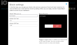
Then click on the Next Step button at the bottom. This lets you define a display name for the block, plus make sure the data values it uses are correct.
Enter a Block Title if you want. Leave the Button On and Button Off text as they are. Feel free to change those values later, but know that you will have to change the code when you are handling the messages.
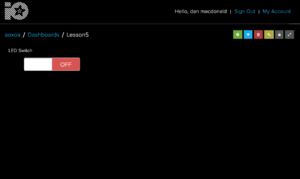
Lastly, press the Create Block button at the bottom. Your finished Dashboard is ready:
Collect Your Authorization Information
That last thing you need to do is check your Username and Key for access the feed remotely. Click on the View AIO Key link on the left side of the screen. Use copy and paste to save the key (especially) - you will need to enter both the username and the key into your program.
Testing and Using Your Dashboard
To use the dashboard, go to the io.adafruit.com website either from a computer, or from an internet enabled phone. Log in, and find your Dashboard named Lesson5. Now whenever you switch from ON to OFF and vice versa, the Adafruit Cloud will send a message to any devices that have subscribed to the LedSwitch datafeed.
So let's create the circuit and the program now....
Wifi Connection Parameters
You will need to the the Wifi SSID (wifi network name) and the password required to connect to the network. If you change networks, such as moving from the Scout Hall, to home, and then back again, you will need to update the code to use the appropriate wifi name and password each time.
Create the Circuit
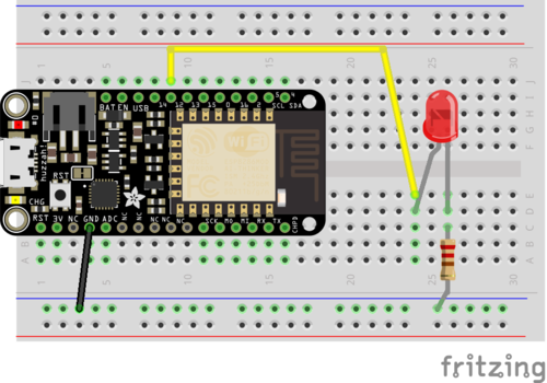
We can use the same circuit as we created for the external LED lesson:
Enable Some Libraries
We need three additional libraries within the Arduino IDE. So start up the IDE, and go to Sketch -> Include Library -> Manage Libraries...
Scroll down to find the Adafruit IO Arduino, then click the Install button (if you can't, select the latest version from the dropdown list).
Then scroll down and do the same for the Adafuit MQTT Library.
Finally, do the same for the ArduinoHttpClient library.
Note: There may be a requirement for a specific version of the ESP8266 Board software (that we installed in Lesson 1). You might want to check that Tools -> Board -> Boards Manager has version 2.4.2 Installed for the esp8266 boards.
Create the Program
I will explain the code pieces first. The complete program is at the end.
Initializing and Using Serial Output
We have not needed it yet because out programs have been pretty simple, but sometimes you need to see what a program is doing, as it executes, to figure out why something is not working correctly. Many modern development IDEs have 'debuggers' where you can manually execute your code line by line; unfortunately, because our code is uploaded and runs on the Huzzah microprocessor, that is not an option. So we have to revert back to the old fashioned debugging - print statements.
There is an iconic button on the top right over every sketch (it kind of looks like a magnifying glass with a dot in the middle):
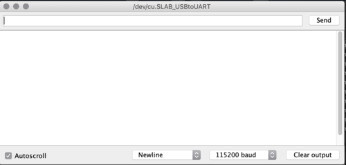
Click that to open another window called the Console. Never open the console when you are uploading a sketch - the upload will fail. Open the console before you upload, or after. When the console opens, made sure it's baud rate is the same as the value you specify in the Serial.begin(); call in your code (or you will see funny looking characters.
In order to use the Console, you need to initialize it within the setup() loop:
void setup() {
   Serial.begin(115200);
   ...
}
Thereafter, whenever you want to print something to the console, you have two options:
- Serial.print("some message");
- Serial.println("some other message");
The difference between the two is that the println() function prints a 'carriage return' at the end of the line, whereas print() puts the text at the end of the current line.
Connecting to the Internet
For this step, you need the name & password to the local Wifi, and your Adafruit IO Cloud username and 'secret key'. Note that you need to use YOUR Wifi SSID and password, and YOUR Adafruit IO username and key.
We need to use the AdafruitIO_WiFi library, so we 'include' the library's ".h" file.
We also create an object that we will call "io" that is the connection to our account in the Adafruit IO Cloud.
#include "AdafruitIO_WiFi.h"

// WiFi parameters
#define WLAN_SSID       "Sidneyhall"
#define WLAN_PASS       "12345678"

// Adafruit IO
#define IO_USERNAME    "aoxoa"
#define IO_KEY         "abcdef123456abcdef1234567890"


/****************************** Feeds ***************************************/
AdafruitIO_WiFi io(IO_USERNAME, IO_KEY, WLAN_SSID, WLAN_PASS);
/****************************** Feeds ***************************************/

void setup() {
  // start MQTT connection to io.adafruit.com
  io.connect();

  // wait for an MQTT connection
  // NOTE: when blending the HTTP and MQTT API, always use the mqttStatus
  // method to check on MQTT connection status specifically
  while(io.mqttStatus() < AIO_CONNECTED) {
    Serial.print(".");
    delay(500);
  }

  // we are connected
  Serial.println();
  Serial.println(io.statusText());
}

void loop() {
  io.run();
}
Subscribing the the Datafeed
Now we add in the code that will connect us to the datafeed that we created earlier. Obviously, you need to know the name of that datafeed....
/****************************** Feeds ***************************************/
AdafruitIO_WiFi io(IO_USERNAME, IO_KEY, WLAN_SSID, WLAN_PASS);

AdafruitIO_Feed *ledSwitch = io.feed("LedSwitch");
/****************************** Feeds ***************************************/
Message Handlers
A 'message handler' is a function that we set up to handle an incoming message or event. Within our program, we don't actually call the message handler directly - instead we connect to the incoming datafeed and when we received something from that feed, our handler is called. If you are responding to multiple datafeeds, then you would have multiple message handlers, one for each datafeed.
In our handler, we get the value of the message sent, and then "trim" it, because "ON" is not the same as "ON ". Trim() will ermove those extra leading and trailing spaces and makes for cleaner code.
#define LEDPIN    12

/****************************** Feeds ***************************************/
AdafruitIO_WiFi io(IO_USERNAME, IO_KEY, WLAN_SSID, WLAN_PASS);

AdafruitIO_Feed *ledSwitch = io.feed("LedSwitch");
/****************************** Feeds ***************************************/


void setup() {
  ...
  // set up the LED pin
  pinMode(LEDPIN, OUTPUT);
  digitalWrite(LEDPIN, LOW);
  ...
  // set up a message handler for the count feed.
  // the handleMessage function (defined below)
  // will be called whenever a message is
  // received from adafruit io.
  ledSwitch->onMessage(handleMessageSwitch);
  ...
  // Because Adafruit IO doesn't support the MQTT retain flag, we can use the
  // get() function to ask IO to resend the last value for this feed to just
  // this MQTT client after the io client is connected.
  ledSwitch->get();
  ...
}


void loop() {
  io.run();
}


void handleMessageSwitch(AdafruitIO_Data *data) {
  Serial.print("ON/OFF received <- ");
  String message = data->value();
  message.trim();
  Serial.println(message);
  if ( message == "ON" ) {
    digitaWrite(LEDPIN,HIGH);
  }
  else {
    digitalWrite(LEDPIN,LOW);
  }
}
Putting It All Together
So the final program should look something like this, with the correct Wifi and Adafruit IO Cloud connection parameters:
#include "AdafruitIO_WiFi.h"

// WiFi parameters
#define WLAN_SSID       "Sidneyhall"
#define WLAN_PASS       "12345678"

// Adafruit IO
#define IO_USERNAME    "aoxoa"
#define IO_KEY         "abcdef123456abcdef1234567890"

#define LEDPIN    12

/****************************** Feeds ***************************************/
AdafruitIO_WiFi io(IO_USERNAME, IO_KEY, WLAN_SSID, WLAN_PASS);

AdafruitIO_Feed *ledSwitch = io.feed("LedSwitch");
/****************************** Feeds ***************************************/

void setup() {
   Serial.begin(115200);

  // set up the LED pin
  pinMode(LEDPIN, OUTPUT);
  digitalWrite(LEDPIN, LOW);

  // start MQTT connection to io.adafruit.com
  io.connect();

  // set up a message handler for the count feed.
  // the handleMessage function (defined below)
  // will be called whenever a message is
  // received from adafruit io.
  ledSwitch->onMessage(handleMessageSwitch);

  // wait for an MQTT connection
  // NOTE: when blending the HTTP and MQTT API, always use the mqttStatus
  // method to check on MQTT connection status specifically
  while(io.mqttStatus() < AIO_CONNECTED) {
    Serial.print(".");
    delay(500);
  }

  // Because Adafruit IO doesn't support the MQTT retain flag, we can use the
  // get() function to ask IO to resend the last value for this feed to just
  // this MQTT client after the io client is connected.
  ledSwitch->get();

  // we are connected
  Serial.println();
  Serial.println(io.statusText());
}

void loop() {
  io.run();
}

void handleMessageSwitch(AdafruitIO_Data *data) {
  Serial.print("ON/OFF received <- ");
  String message = data->value();
  message.trim();
  Serial.println(message);
  if ( message == "ON" ) {
    digitalWrite(LEDPIN,HIGH);
  }
  else {
    digitalWrite(LEDPIN,LOW);
  }
}
Compile and Run
Firstly, start up the console before you compile so that you do not forget.
Then compile and upload the program to the Huzzah.
Now use a phone or a computer to go to your Adafruit IO Cloud dashboard and change the value of the switch, and see what happens.
